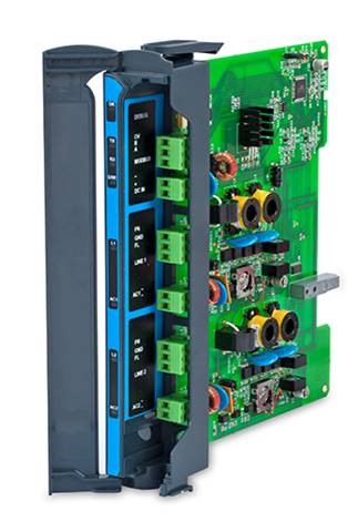
Serial translator
The Aquamonix range of 2-Wire Translators are marketed globally under Tonick Watering.
Tonick translators provide both the power and signaling to a range of field devices via a 2-wire pathway, and are capable of complex control and data collection. Tonick translators can be connected to your control system via a serial MODbus port or a simple multi-wire digital input interface.
The Serial Translator is a true A/C 2-wire decoder for landscape applications, compatible with the Motorola ACE irrigation controller.
- Two outputs that can be controlled independently
- Each output can control up to 127 individually addressed decoders for a total of 254stations
- A RS485 serial bus to communicate with a Modbus RTU protocol
- Operation rated to ambient +70°C
- Suitable for use with Tonick 2-wire TW/2W decoders, MK3 decoders and Decoder-In-A-Solenoid (DIAS)
- Supports a range of sensor input decoders
Electrical
- Supply voltage 24 ~32 V RMS AC 50 or 60Hz
- Supply current up to 1.3A
- Output voltage 23-31 V RMS AC
- Output current max continuous
– 1.2A at +50°C Ambient
– 0.6A at +70°C Ambient
- Recommended inverted power supply is 12VDC – 28VAC, constant, 60Hz
Note: Full Line output voltage will be continuously applied to the solenoids connected to ‘on’ decoders. Attention must be given to the specifications of these solenoids.
Line Signalling
- Up to 127 Tonick 2 Wire decoders, MK3 decoders or Decoder-In-A-Solenoid (DIAS)
- Up to 16 active DIAS 2-Way, 10 active DIAS 3-Way or 4 TW/2W/MK3 decoders and solenoids (subject to total solenoid loads)
- Allow 45 seconds after power-up before switching decoders
- Custom firmware for OEM systems
- Compatible with Tonick decoders and Decoder-In-A-Solenoid (DIAS)
- Compatible with all Tonick sensor decoders for moisture, pressure, water level, flow and digital inputs
- Jumper link pairs J5 and J8 alter the polarity of the decoder signaling waveform on lines 1 and 2
CPU
- 8-bit RISC. 8MIPs, 64K flash / 4K RAM / 4K EEPROM
Firmware
- Re-writable application in general flash space. Uses Kanda Keyfob programmer
Communications
- RS485 half-duplex (+-80V fault, 15kV discharge)
- 9600 Baud, N,8,2 (other formats on request)
Isolation
- 1KV between decoder line/ transformer AC input and RS485 circuitry
Slave Address Programmable
- 1 or 2 using the jumper able link marked J11. Factory Set: Slave address 1
Connections
The Serial Translator should be wired as follows:
- AC1 and AC1 terminals should be wired to the transformer supply
- FL1 is the Field Cable 1 ‘Live’ terminal (referred to as the ‘line’)
- FN1 is the Field Cable 1 ‘Neutral’ terminal
- EST1 The Earth Stake terminal (EST) MUST be connected to the earth stake EST1 and EST2 can be connected to just one earth stake. (see below for recommendations)
- AC2 and AC2 terminals should be wired to the transformer supply
- FL2 is the Field Cable 2 ‘Live’ terminal (referred to as the ‘line’)
- FN2 is the Field Cable 2 ‘Neutral’ terminal
- EST2 The Earth Stake terminal (EST) MUST be connected to the earth stake EST1 and EST2 can be connected to just one earth stake. (see below for recommendations)
- A (D0), B (D1) are half duplex RS485 signals B is +ve and A is -ve during line idle conditions
- COM is the ground of the RS485 circuitry and must be connected to the RS485 0V of host controller. The 0V of the interfaces’ comms is within +/- 1.5V of the Output 1B
- The RS485 is optically isolated from the Tonick BT2 decoder circuits by at least 1KV to help protect against lightning surges propagating in the host controller
- Auxiliary Output 1B. This supplies the Motorola ACE 2Wire CPU and RS485 circuits. FL1, FN1, FL2, FN2 are optically isolated to 3kV from the Auxiliary Output 1B
Grounding System
- The Earth Stake terminal (EST) MUST be connected to a properly bedded earth stake or plate via a 4mm2 (#11 AWG) or larger earth wire. This earth system is not to be regarded as an electrical safety earth. Connection of the EST to a building and/or an electrical earth is NOT permitted
- Use of the Tonick Line Terminating Unit (LTU) at each termination of the 2-wire path is recommended to complete the lightning protection system
Environmental
- Storage – 0 to 70°C 5% to 95 % humidity (non-condensing)
- Operation +3 to +70°C, de-rated from 1.2A output at +50°C to 0.6A output at +70°C, 5 to 95 % humidity (non-condensing)

